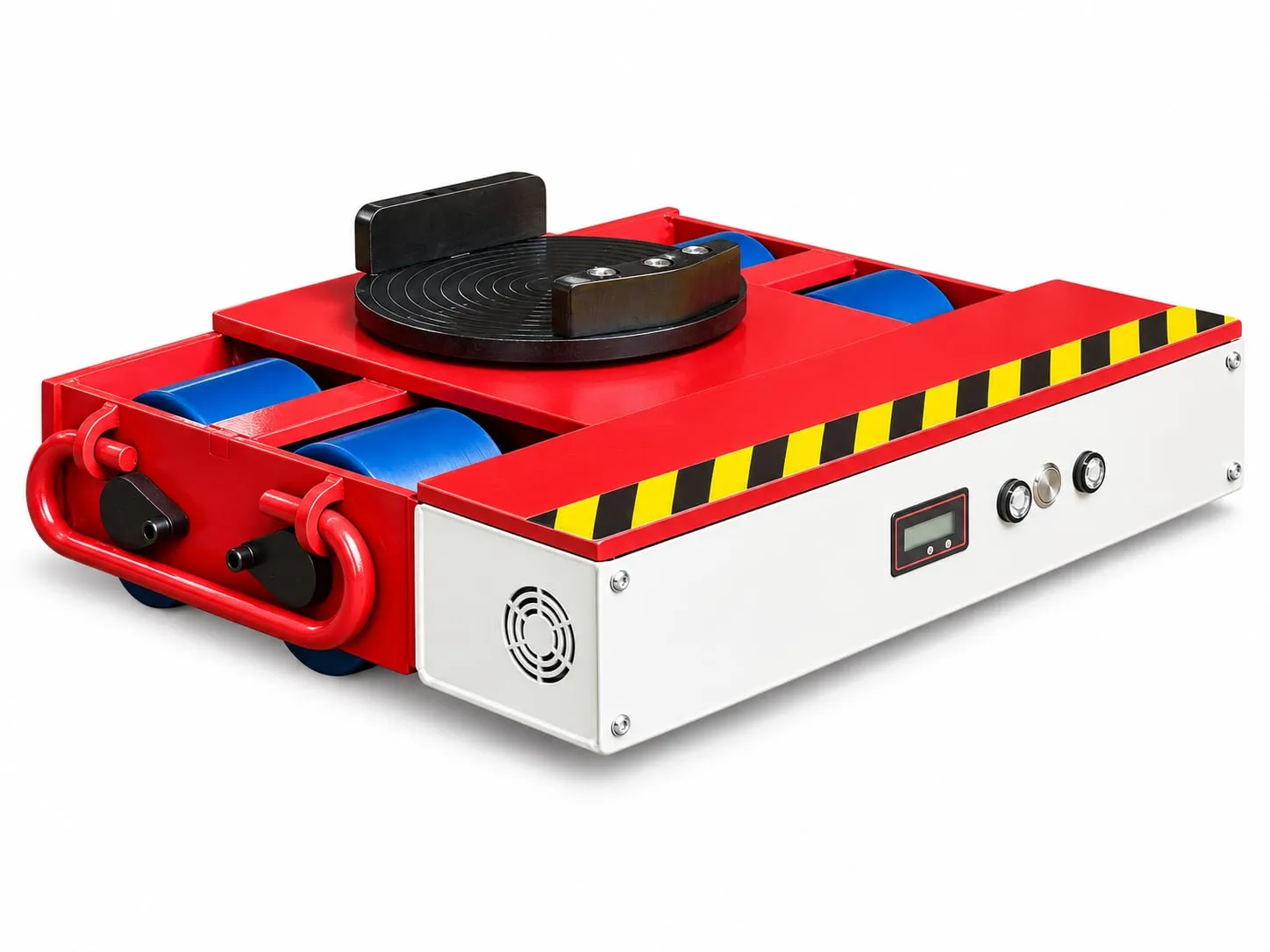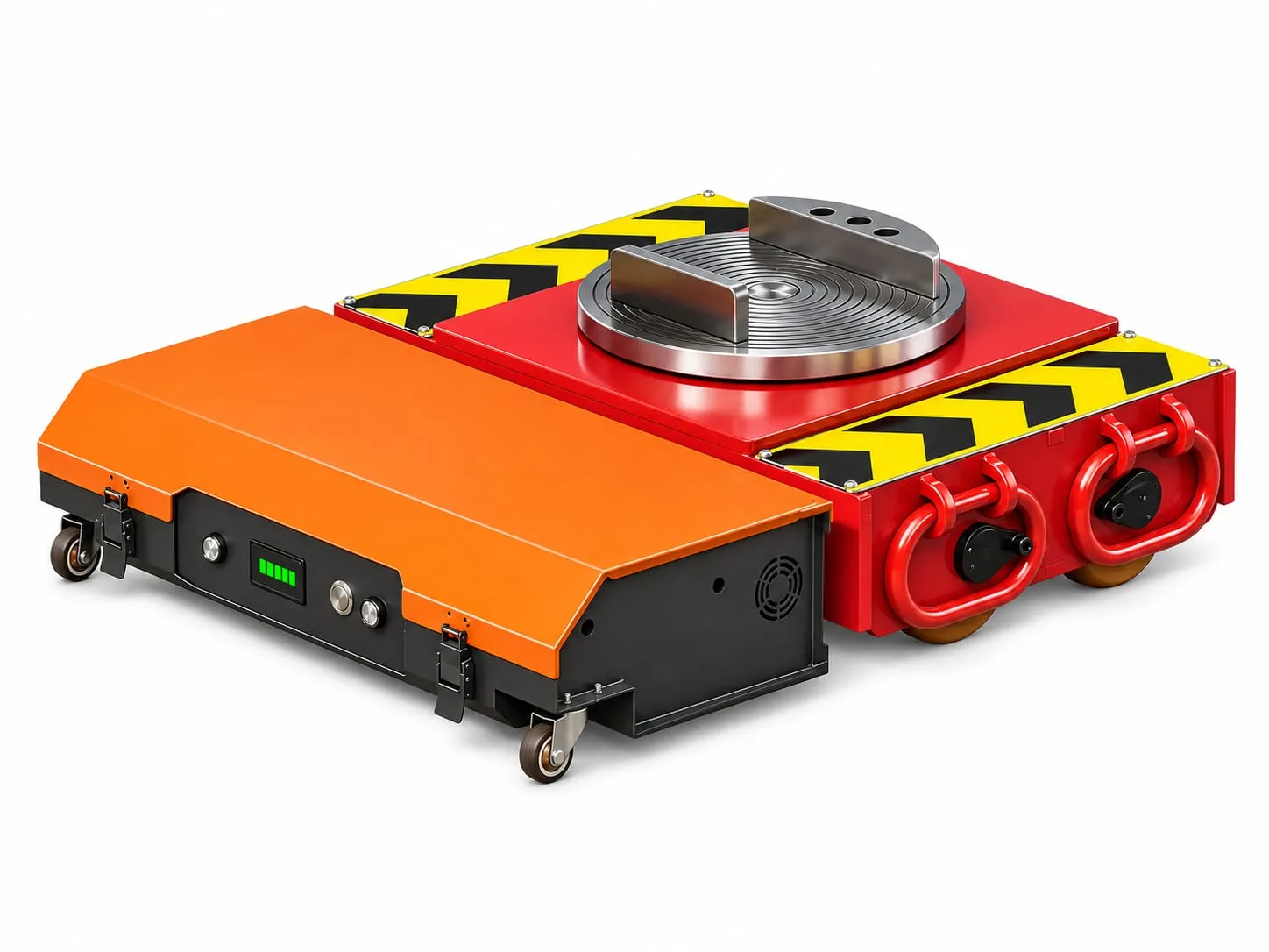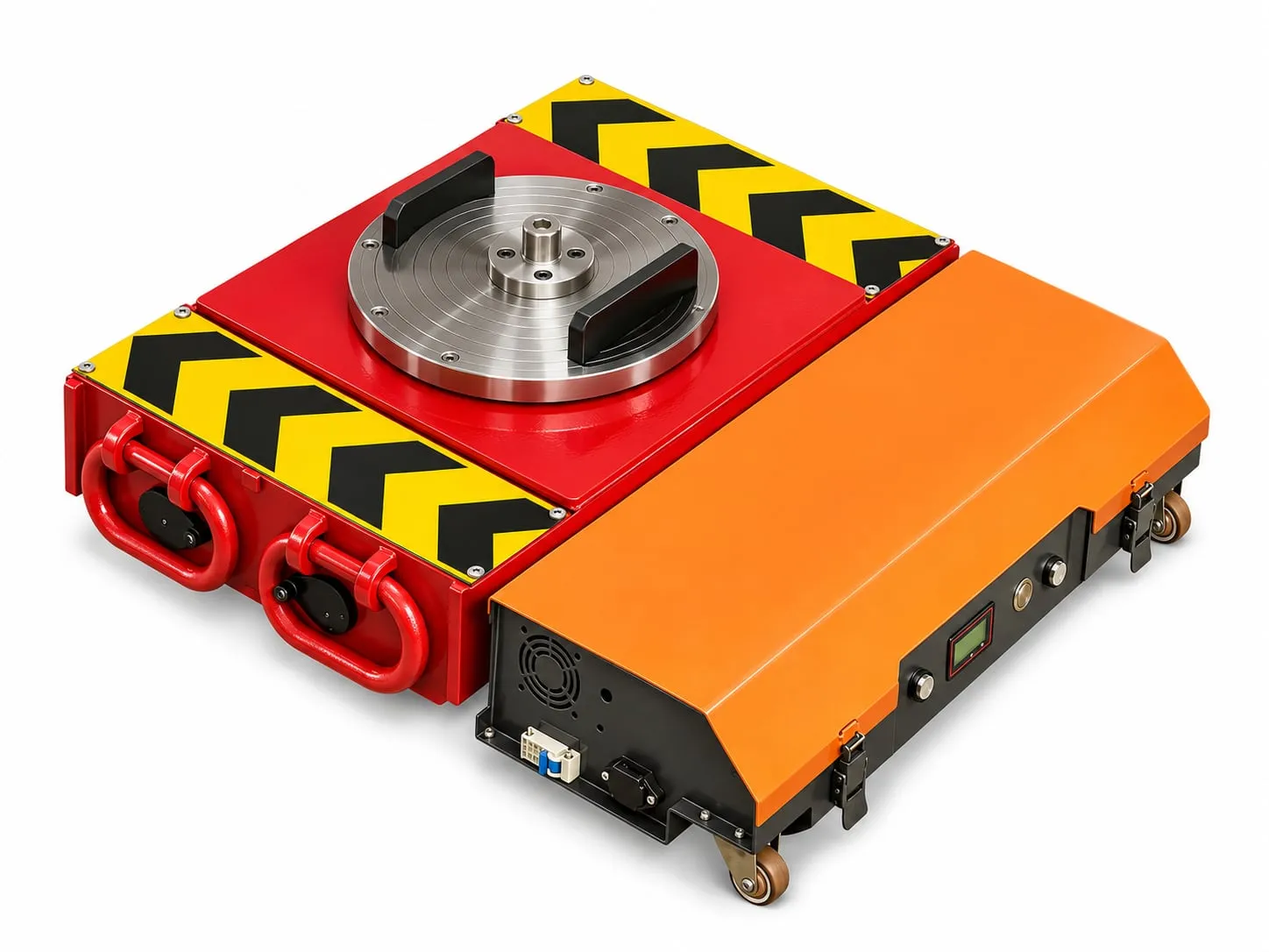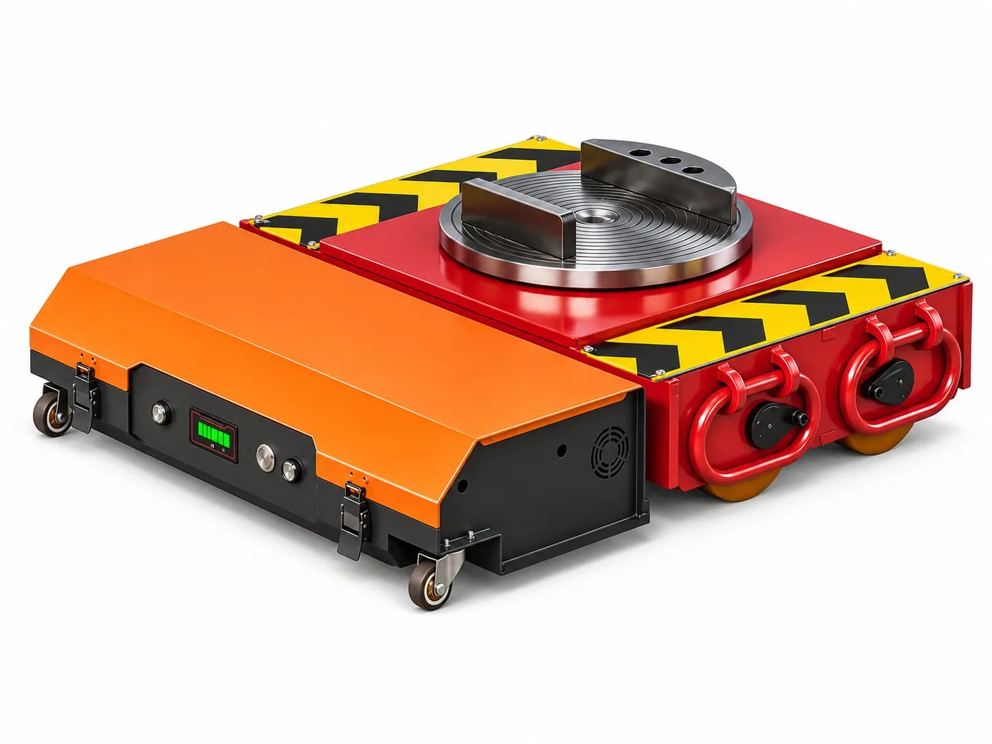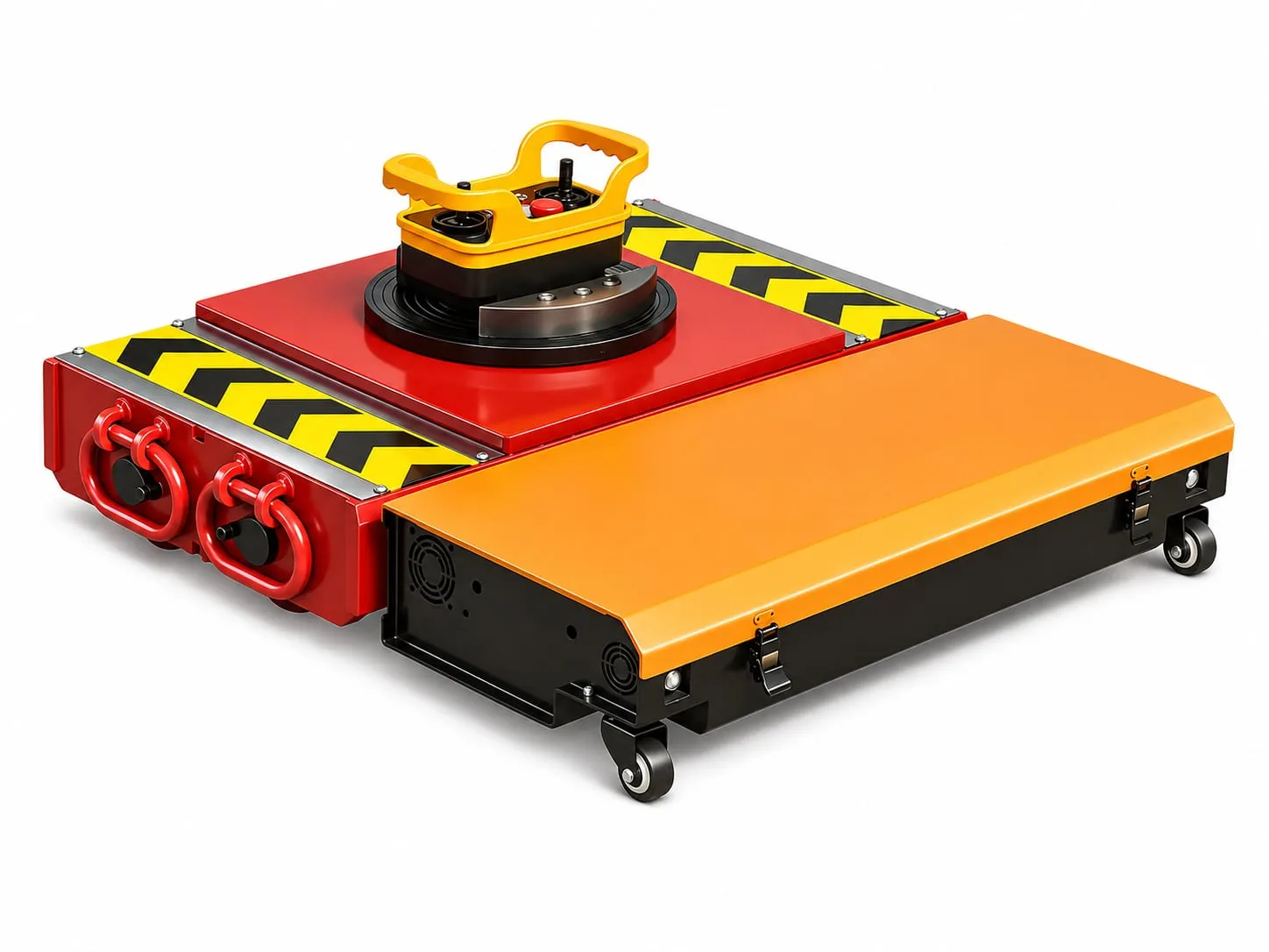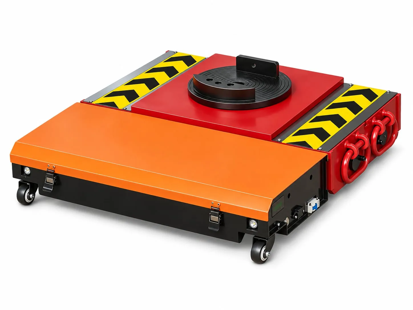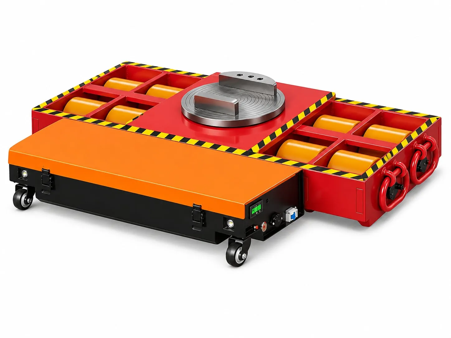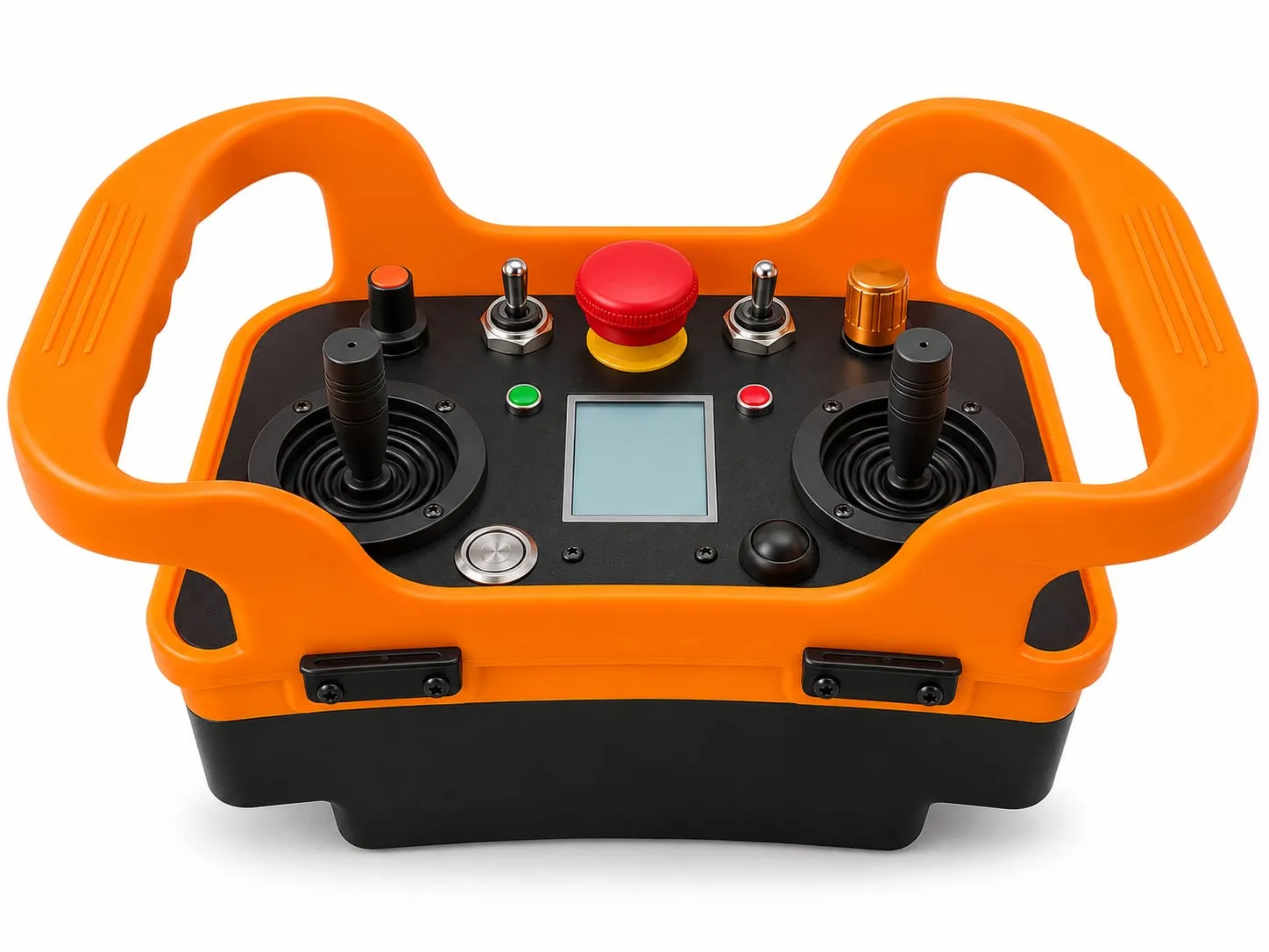
Short answer: For machine tool installation, jack the machine at its lifting points, set an electric tank mover under the heavier end and two auxiliary cargo trolleys under the other, and drive it from the truck bay to its foundation by remote control. The 360° turntable handles corners and the 2 m/min creep speed handles the final approach.
Where tank movers fit in a machine installation
Installing a new CNC machining centre, lathe, grinder or press usually breaks into three moves: off the truck, through the building, and onto the foundation. Riggers often have a forklift or crane for the first and last metres, but the middle part, through doors and down narrow aisles past running machines, is where loads get stuck.
An electric tank mover covers that middle part. Its deck is only 145–185 mm high, depending on the model, so a machine needs only a short jacking stroke. Two geared motors with brakes drive it at 2–10 m/min, and a 48 V lithium battery gives 2–5 hours of run time. The operator walks beside the load with the remote and can see both ends.
Before move day: the checks that matter
Machine data. Get the weight, footprint and centre of gravity from the maker’s installation manual or foundation drawing. Machine tools are rarely balanced: the spindle head, column or tool changer usually makes one end heavier. Note the approved jacking or lifting points. Never jack under sheet-metal guarding, chip conveyors or coolant tanks.
Doors and aisles. Measure the clear width and height of every door. Compare them with the machine’s widest point and add room for the operator and a spotter. Long machines turning through a door need extra width. Draw the turn on the floor plan, because the trolley end swings wider than the mover end.
Floor and foundation. Confirm the floor can carry the wheel loads, and protect fresh foundations: the movers should stop on solid floor beside a new pad, not drive onto concrete that has not fully cured. Cover cable trenches, joints and pit edges with steel plates.
Slopes and docks. Factory guidance for ramps is up to about 15°. Loading docks, dock levellers and yard ramps should be checked with us.
The UK HSE requires lifting operations to be planned by a competent person, supervised and carried out safely. Treat the jacking stage as part of that plan.
Choosing the set
Size the tank mover for the heavier end of the machine. The model number is what the whole set can move; the tank mover itself carries half (for example 15 t on a TM-30).
| Machine | Typical weight | Suggested set | Tank mover carries up to |
|---|---|---|---|
| Lathe, grinder, small press | Up to 8 t | TM-20 + 2 trolleys | 10 t |
| CNC machining centre, press brake | 12–18 t | TM-30 + 2 trolleys | 15 t |
| Large VMC or HMC, bridge mill | 20–35 t | TM-40 or TM-50 + 2 trolleys | 20–25 t |
| Gantry mill, large press frame | 35–60 t | TM-60 + 2 trolleys, or a 2 + 2 set | 30 t per tank mover |
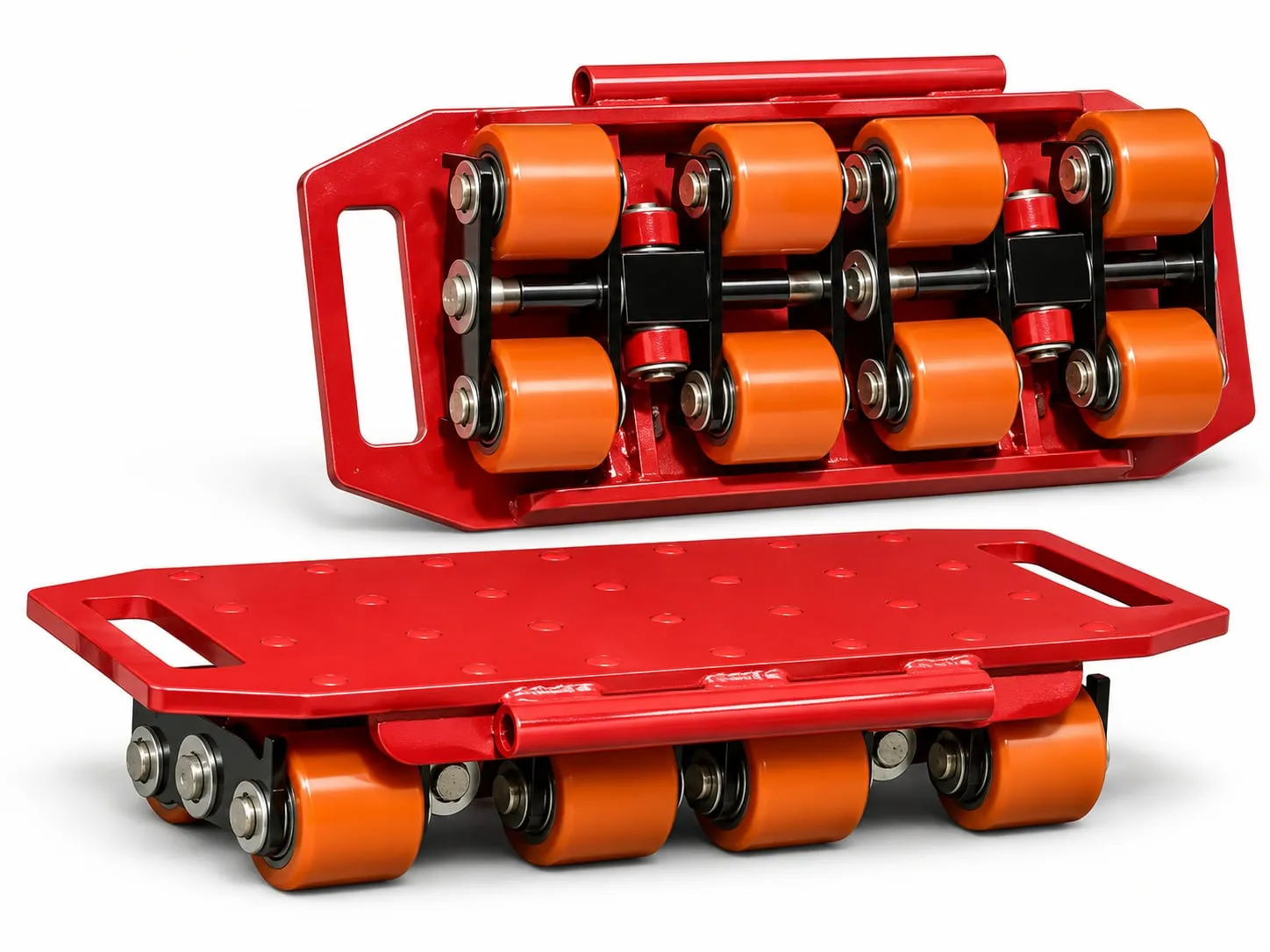
Pick auxiliary cargo trolleys for the other end: the 4-roller (12 t) and 6-roller (18 t) units pair with sets of 10–30 t, the 8- to 12-roller units (24–36 t) with 30–60 t sets.
Step by step: truck bay to foundation
- Unload with a forklift or crane, or roll off a dock, and set the machine on cribbing.
- Jack evenly at the approved points with claw or hydraulic jacks (a 48 V lithium hydraulic pump is available), using cribbing as you go.
- Place the movers: tank mover under the heavy end on a solid casting, auxiliary trolleys square under the other end.
- Lower and check that the machine sits level and stable, then remove the jacks.
- Travel at low speed through doors, with a spotter at the trolley end.
- Turn on the turntable at aisle junctions; stop, check clearance, continue.
- Final approach at about 2 m/min to the marks beside the foundation.
- Jack off, remove the movers, set the machine down and hand over for levelling and anchoring.
The industrial remote is worth adding for installations: the 0–10 speed dial gives finer control on the final approach, and its emergency stop is in the operator’s hand.
Tank movers compared with other installation methods
| Method | Indoor reach | Turning in tight aisles | Crew | Main limit |
|---|---|---|---|---|
| Electric tank mover set | Any flat route | 360° turntable | 1 operator + spotter | Jacking on and off |
| Forklift | Good for light loads | Needs turning space | Driver + spotter | Capacity and counterweight |
| Gantry or overhead crane | Only under its own span | Not a factor | Crane team | Fixed coverage |
| Manual roller skids | Any flat route | Hard to steer | Several people | Pushing, stopping and steering |
For a fuller comparison see tank movers vs forklifts, cranes and rollers.
Example: installing a 14 t machining centre
Example (illustrative numbers, not a customer job): a vertical machining centre weighs 14 t. The column end is heavier, carrying 65% of the weight.
- Column end on the tank mover: 14 t × 0.65 = 9.1 t. A TM-30 carries 15 t, leaving a comfortable margin.
- Table end on two auxiliary trolleys: 14 t × 0.35 = 4.9 t, about 2.5 t each. Two 4-roller trolleys (12 t each) are more than enough.
- Route: 60 m from the dock to the foundation at 4 m/min is about 15 minutes of driving, plus stops at each door. The TM-30’s 3–4 h run time covers this with a large reserve.
Why not a TM-20? Its tank mover is rated at 10 t, only 0.9 t above the 9.1 t column end, and the weight split on a real machine is often less certain than on paper. The full method is in how to size an electric tank mover set.
Safety checklist
- Written move plan, with weights, jacking points and route, agreed before work starts.
- Nobody between the machine and walls, columns or other machines while it moves.
- Raised loads always on cribbing, never on jacks alone.
- Tall machines and loose parts (doors, tool magazines, tables) secured for travel.
- Emergency stop tested before the first lift.
For the full method read how to move heavy machinery with tank movers, and for budgets the price and buying guide. Send us the machine data and a sketch of the route and we will recommend a set: contact us.